These options provide additional criteria to help distinguish between rail types when the base portions are identical, or too similar to be reliably differentiated on the basis of fit.
If the measured rail exceeds the rail selection option values for a given unworn rail type, the fitting error is increased, and the probability that it will be selected as that type is reduced. A table of weighting factors used to adjust the fitting error based on rail selection options is given at the end of this section.
Head Over Height limits the amount by which the height of the measured rail may exceed the height of the unworn rail. A slight excess should be expected when measuring new rail, because rail is often rolled slightly larger than its nominal dimensions. If two rail types are identical in base, fillet, and web, but have different heights, head over height may help to distinguish them. It will only work, however, for the higher rail type, and only until it is worn down to the height of the lower type plus head over height.
Head Under Height limits the amount by which either face of the measured rail may extend below the face of the unworn rail. When setting this parameter, bear in mind not only that the rail may not have been rolled quite to its nominal dimensions, but also that vertical plastic flow may extend well below the original bottom surface of the rail head. This happens most often in areas of severe gauge face wear. For that reason, the head under height option is often set very permissively, to 0.5 in. (12.7 mm) or more.
Under Both Sides limits the amount by which either face of the measured rail may extend below the face of the unworn rail on both sides. This is useful in areas where plastic flow on curve-worn rail extends substantially below the bottom of the unworn head on the gauge face, making the 'head-under height' test useless. Even transposed rail will rarely have vertical plastic flow on both sides. It is almost always safe to set 'under both sides' to an aggressively small value such as 0.5 mm or 0.020".
Face Angle Difference is the allowable angular difference between portions of the rail face that appear unworn, and the face of the nominal rail type. Face angle helps to discriminate between profiles that may be very similar in base, fillet and web - for example, 136 RE and 141 RE, which are identical below the head. The nominal face angle of 136 RE is 1:40, or 1.43 degrees, whereas the face angle of 141 RE is 5 degrees. The option should be set to 1 or 2 degrees to be useful.
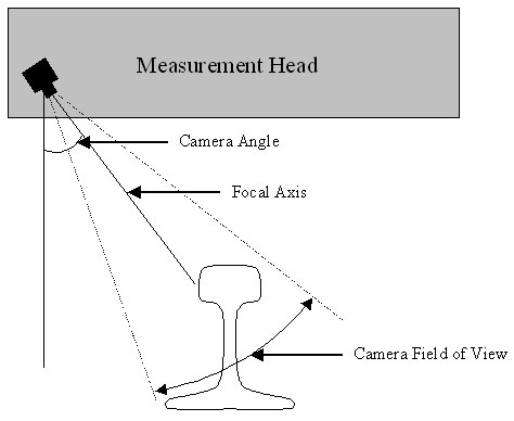
Unlike other rail selection options, Camera Angle is directly related to the geometry of the optical rail measurement system. It is the angle of the cameras focal axis, relative to vertical, in a front-view projection.
The camera angle is used to help prevent misidentifications where the measured shape could not possibly be seen by the camera because of occlusion by the lower corner of the head.
Caution: because the cameras viewing angle varies across its field of view, the camera angle should be set to a value several degrees higher than the design camera angle of the measurement head. A camera angle setting of 43 degrees usually works well for profiles measured by Laserail or ORIAN equipment.
Web Thickness Over is the amount that the measured web thickness may exceed that of the unworn profile without increasing the fitting error. Web thickness is calculated by fitting circles to each web, then subtracting both radii from the horizontal distance between the center points.
Web Thickness Under is the maximum amount that the measured web thickness may fall short of that of the unworn profile without increasing the fitting error. If the measurement system is out of calibration, it may consistently measure web thickness as too thick or too thin. In that case, you can improve rail-type discrimination by using different values for 'web thickness over' and 'web thickness under'.
Fillet Radius Over is the amount that the fitted fillet radius of the measured profile may exceed the nominal fillet radius of the unworn profile. A radius that exceeds this margin will increase the fitting error.
Fillet Radius Under is the amount that the fitted fillet radius of the measured profile may fall short of the nominal fillet radius of the unworn profile. A radius smaller than this margin will increase the fitting error.
Weighting factors are applied to values in excess of the rail selection options, according to the following table.
|
Option |
Weighting Factor |
|
Head Over Height |
0.50 per mm |
|
Head Under Height |
0.05 per mm |
|
Under Both Sides |
0.40 per mm |
|
Face Angle Difference |
0.10 per degree |
|
Camera Angle |
0.10 per degree |
|
Web Thickness Over |
0.10 per mm |
|
Web Thickness Under |
0.10 per mm |
|
Fillet Radius Over |
0.05 per mm |
|
Fillet Radius Under |
0.08 per mm |
Different weights apply to different tests according to their reliability in discriminating between rail sections. Since actual rail is hardly ever much taller than its design height, a strong weighting factor is applied to the Head Over Height test ten times as strong as the weighting factor applied to the Head Under Height test, which, as mentioned, may be affected by vertical plastic flow.
The way the weighting factors work is best illustrated by an example. Suppose a rail profile is fit to a 136 lb section with a fitting error of 0.8. The profile is measured as 1.3 mm taller than the unworn 136 RE profile, and the Head Over Height option is set to 1.0 mm. The difference (0.3 mm) times the weighting factor (0.50 per mm) is 0.15. This value, along with all other results of the rail selection tests, is added to the fitting error, yielding a total error of 0.95.
This process is repeated for all the selected rail types. The profile is then identified as the rail type with the lowest total error provided that the total error does not exceed the Maximum Fitting Error setting!
The last Rail Selection option, Use Imported Type, allows the rail section, if any, identified in the import source file to influence the rail selection process. This percentage value reduces the error term calculated by Rangecam for the imported rail type. If set to 100%, it reduces the error term to 0, with the result that the imported rail type will always be selected (unless the measured profile is so incomplete or distorted that Rangecam cannot fit it to the unworn rail shape at all). If set to 0% (the default), Use Import Type has no effect. Rangecam will ignore the imported type and make its own selection. If set to an intermediate value, Rangecam will reduce its own error term for the imported type by the percentage entered.
For example, suppose that Rangecam calculates the following total error terms for a given profile when fitting it to the rail sections 115 RE, 132 RE and 136 RE:
|
Rail Type |
Total Error (calculated by Rangecam) |
|
115 RE |
1.4 |
|
132 RE |
0.5 |
|
136 RE |
0.7 |
In the import source file, this profile is identified as 136 RE, and the Use Imported Type option is set to 40%. The final error term for 136 RE is then reduced by 40% of 0.7, to an adjusted value of 0.42. In this case, 136 RE will be the selected rail type. But if the option were set to 20% instead, the adjusted error term for 136 RE would only be reduced to 0.56, and 132 RE would be selected. The following table summarizes this situation:
|
Rail Type |
Total Error (Rangecam) |
Adjusted Error if Use Import Type = 40% |
Adjusted Error if Use Import Type = 20% |
|
115 RE |
1.4 |
(unchanged) |
(unchanged) |
|
132 RE |
0.5 |
(unchanged) |
(unchanged) SELECTED |
|
136 RE |
0.7 |
0.42 SELECTED |
0.56 |
Note: the Use Imported Type option is currently only supported for Laserail source files. Also, its use requires a customized version of the INI file (RI_LR*.INI) used in the import process. The customization is needed to specify how rail type IDs in the import file, which are customer-specific, are translated into the rail type IDs known to Rangecam. To obtain a customized version of the INI file, please contact Holland LP.
For further information as to how the rail selection options work, see the above section, Interpreting the Run Statistics.